Showing posts with label Maintenance. Show all posts

Cleaning The Top-End (Decoking)

This tutorial will demonstrate the process of decoking the top end, or removing the carbon deposits from the engine. This is a standard maintenance and should be performed every 6000km (4000 miles), or every year for machines that are never heating up (quick hops about town). It will be virtually impossible to get all the crud off of the engine parts, so don't be overly compulsive about it. Though the process seems daunting, like putting a wheel together, it is one of those chores that you will be able to fly through after your first go. I would give it a few hours for the first time. I hear some asking, "why should I do this; my engine runs fine?" This procedure is important because of the heat and power restrictions a two stroke engine has to contend with. By letting junk build up on the piston, cylinder and head, you are effectively decreasing the fuel capacity of your motor (ie 200 cc to something slightly less). Since waste carbon, commonly called coke, is left from burning two stroke oil, the engine will suffer from an overly "rich" condition and generally run badly or start hard. A few signs that your top-end may need to be cleaned are oily, constantly fouling spark plugs; hard starting (more than 4 kicks) and lots of exhaust smoke. I would reccomend you preced this operation with a carb rebuild when attempting for the first time. Synthetic lubricants will increase the period of this procedure, but it is still worthwhile to consider attempting every year. This procedure is best done in a covered, well lit area (like a garage) so no crap gets into your top end.

Tools & Parts Needed
Multi Screwdriver
Spark Plug Wrench
Disposeable Shop Towels
A can of Carb Cleaner
A Tube of Anti-Sieze Lubricant
13mm and 11mm Deep Socket
Torque Wrench (Absolutely neccessary, DO NOT perform without this item)
Plastic Bondo (Body Filler) Scraper
Plastic "Wire" Brush
Tub of All-Purpose / Bearing Grease ("Green Goop")


Procedure
The Carb Box
Step 1

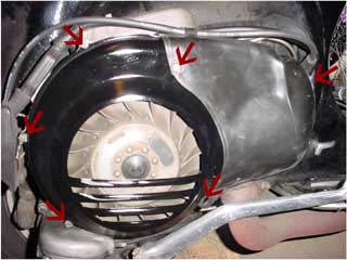
Undo the arrowed screws and the flywheel shroud will fall right off. Put the shroud and all the little screws in a safe place (or sand it down and paint it if you have a day or two).


The Carb Box
Step 2

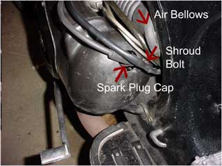
Gently prise off the spark plug connector and put it one side. Undo the Shroud bolt right next to the spark plug. Unhook the air bellows from the frame and push it to one side. Slide the cylinder shroud off of the engine by pulling towards the front of the bike. You should now be able to see the cylinder. Remove the sparkplug with the sparkplug wrench.


The Carb Box
Step 3

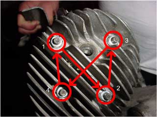
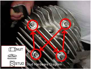
Remove the nuts by loosening them slowly in this order. Do a quarter turn, go to the next, quarter turn, next, quarter turn, next, etc. until the nuts are removed. This will take a while, but you risk bending the aluminum head if you don't do them in small steps and in order. The same is true for tightening. Carefully collect the hardware and remove the cylinder head.


The Carb Box
Step 4

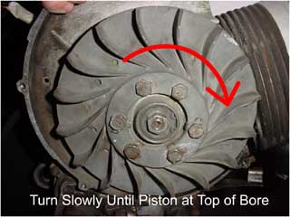
Since the flywheel is connected to the crank, you can raise and lower the piston simply by turning the flywheel by hand. To start, position the piston to the top of the bore. You are now ready to start cleaning.


Cleaning the Air Filter
Step 5

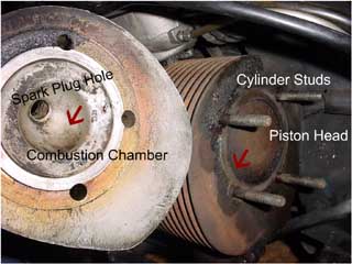
With the piston at the top of the bore, rub a ring of all purpose grease around the circumference of the piston head. This will catch any little chunks of carbon. If your piston is totally coated in carbon (like mine) use a plastic scraper to get most of the crud off. When you are done scraping, remove the remainder with a plastic "wire" brush. Metal is NOT reccomended.


Inspecting the Fuel Filter
Step 6

Wipe off all of the grease from the scraping. To clean the sides of the piston and bore, apply another ring of grease and turn the flywheel slowly. The piston will recede into the bore. Go halfway down, rub away some of the grease with a disposeable towel then go to the bottom and repeat. Keep re-applying grease until the metal on the bore is clean.


Time to buy a new filter when...
Step 7

To clean the cylinder head, use copious amounts of carb cleaner and shop towel, the carbon doesn't tend to stick quite as badly to the head and there's more room to work on it. This part, if any, should be sparkly aluminum grey by the end. Once you finish cleaning the head, spread some anti sieze lubricant (stops threads from stripping) on the thread on the cylinder studs.


Getting the float apart
Step 8

Put the head back on. Hand tighten the screws in order until each becomes snug. Then, using the quarter turn method, tighten the screws with a torque wrench, in order, using a torque of 1.7-2.2 kgf m (12.30-15.91 lbf ft). Re assemble the bodywork in the reverse order. Install the Spark Plug last and reconnect the bellows be stretching the rubber around the lip on the frame.


Once all the panels are back on the bike, kick start the engine as usual. The engine should roar to life after a few kicks. If the kickstart lever doesn't feel firm or if the the engine will only run when the choke is turned on, you have an air leak. This will probably be caused by the sparkplug not beiJustify Fullng tight enough (*The plug is touchy, don't tighten it too strongly or you will rip the threads out of the aluminum*). If you did rip the threads, there will be a leak around the damage -- take the piece to a machine shop and have them install a "helicoil insert", and remind them of the fact it is a cylinder head so they can use a high heat transfer coil. This will replace the old threads and make a much stronger thread. If the plug IS seated properly, the cylinder head may be warped from improper tightening. IF YOU FOLLOW THE RULES, THIS WILL NOT HAPPEN. However, if it is warped, you will need some 400 grit wet/dry sandpaper and a piece of glass. Tape the paper to the glass and wet it. Hold the cylinder head in your palm and rotate the bottom on the paper until it is flat. Once you are done remount it and try again. This maintenance should be done yearly for year round riders, every 6000km (4000 miles) for the "rally only" types.


www.vespamaintenance.com
Read more...
Vespa P200 Two Stroke Primer

Welcome to my primer on two strokes. The Vespa P200 engine is a good example of a by the book rotary valve two stroke. There are only 3 moving parts in the engine's top end: no pushrods, no camshafts, no lifters, nothing you would expect to see in a 4 stroke automobile engine. In this document, I hope to enlighten even the mechanically inept on how these beasts work.


The Parts


If you have ever gotten that feeling that people around you are speaking an alien language when it comes to their bikes, they're probably talking about the engine. :) Never fear, however, I have the cure. Let's have a look at the parts in the engine top-end:

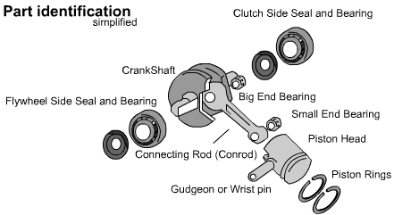
First thing on the roster is the barrel, or bore, or jug - however you may have come to know it. This is the container that holds back the huge forces behind the combusting gas and directs them to the piston. This part is centered with cylinder studs and is highly polished (or honed) to allow the best seal possible. If the polished area is scratched or burnt from overheating, it can be fixed by oversizing. Oversizing can be done at specialty shops and involves machining a larger hole through the bore and buying a larger piston to fit.

Secondly, we have the piston. The piston is made of aluminum alloy and moves up and down inside the cylinder barrel, channelling the force of the combustion into the rod beneath it: the connecting rod. The rings that skirt the piston head are called piston rings. The piston rings form a tight seal to prevent gas from escaping and center the piston head in the barrel. The gudgeon pin, or wrist pin, connects the piston head to the connecting rod.

Speaking of the connecting rod, we will look at that for a minute. The connecting rod is also made of a light metal and transfers the power from the piston and pushes on the crank. There are two bearings on the connecting rod, or con-rod, the small end bearing, or the wrist bearing; and the big end bearing, or the crank pin bearing. These bearings allow a nice circular motion that occurs as your piston moves up and down inside the cylinder.

The crankshaft, or crank is another moving part within the engine. This component has an offset point, called the crank pin , inside it which turns the up-and-down motion of the piston into rotational motion necessary for gears and wheels. The crank is usually made of a really heavy metal, like steel. The crankshaft also plays a part in injecting the gas into the expansion chamber (the place where the piston lives).

The combustion chamber is the place where the compression and combustion of the gas mixture occurs. This part is in the head of the cylinder and looks like a hemisphere (see below). This is the part that your spark plug threads into.

The expansion chamber is the length of the exhaust pipe. The exhaust pipe is approximately 12 times the volume of the displacement of your engine and is 'tuned' to give you the largest power bands. The reason for this phenomenon is that the expansion the combusting of gas is turned into force on the piston, but the gases from the combustion have to escape before the engine can take in new gas. The onus is on the exhaust to facilitate quick removal of the expended gas. The exhaust itself will be tuned such that it will contain exactly the right amount of waste vapours. This creates a pressure difference, that lets some of the exhaust gases leave the pipe and the some get pulled back into the cylinder with the new charge. The strength of this back pressure will result in better or worse performance from your motor. This is why better (tuned) exhausts are soughtafter: the stronger the back pressure, the more efficiently the engine works.

When people talk about 'good compression', they are indicating that the engine is probably in good health. Good compression means that the piston rings are well compressed and sealing properly, the cylinder head and bore are sealed well, the spark plug is tight, the engine seals are tight and the exhaust is providing good back pressure. You can test compression with a compression tester. this device measures the change in pressure when the piston reaches the top of the cylinder. A stock vespa engine typically has a compression of about 120psi. It takes 90psi minimum to start the bike. You can change the compression ratio of the motor by using different cylinder heads and maintaining the piston rings. This higher the compression ratio, the more pressure you will get, but heat will build up faster.


The motions


Induction

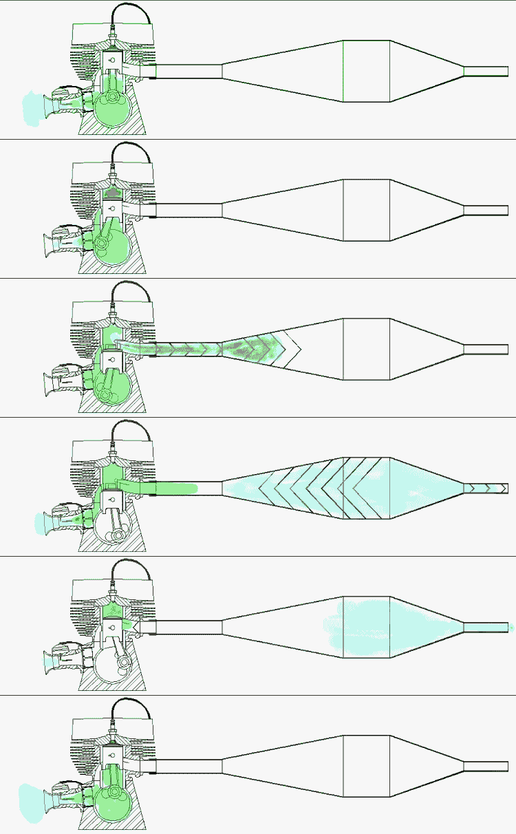
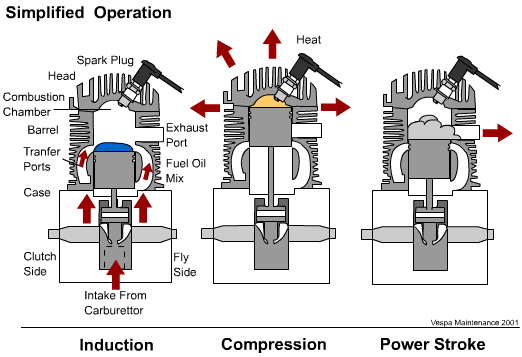
The engine on the P200 uses a 'disc valve' carburettion system and a 'rotary valve' induction system. What the hell am I talking about? I will explain. Disc valve induction from the carburettor is the slide moving in and out of the venturi letting more or less gas get through the hole in the bottom of the carb. Conversely, Rotary valve induction is the cut-out in the crank (you can see this if you turn your flywheel with the carb disassembled) that pulls in the gas being let through the disc valve at exactly the right time.
The efficiency of the rotary valve's seal is based on the rotary pad. the rotary pad is directly below the carbuerettor inlet. This is an extremely high precision part of the motor. if it becomes scratched or dented from an engine failure, the motor will not seal well and you'll lose what is known as primary compression, the compression caused by the rotary valve and engine pressure.
The engine demands a certain amount of fuel from the carb by forming a large low pressure reigon. this low pressure draws gas and air through the carb and into the motor. As the rotary valve closes, the piston has lowered in the cylinder and thus the pressure in the cylinder has changed. Therefore, the fuel mixture rushes into the cylinder. The pressures in the motor move the mixture up through the transfer ports, or channels in the bore, and onto the piston head. The purpose of the fuel mix is two-fold. Obviously, the gas is going to be burnt; however, before that happens, the two stroke oil in the gas lubricates everything it touches. The two stroke oil also forms a heat resistant shield over your piston, protecting the head surface from the gas explosion. Unlike a four stroke engine (like that in a car), a two stroke engine top-end is NOT lubricated by the gearbox oil. This is why two stroke oil has to be added to the gas. If there is no two stroke oil, or you are 'running lean', your engine will very quickly overheat and seize, and/or blow a hole through the piston.


Compression

With the gas collected, the piston continues it's travel up the bore. The heavy flywheel turns the crank and pushes the con-rod, and subsequently the piston, to the top of it's travel. As the piston reaches the top, the gas becomes compressed against the hemispherical area called the combustion chamber. Now we get into timing. When we talk about timing, we are observing the firing point of the spark plug. Ideally, the firing point should occur as the piston reaches the top dead center (TDC) of its travel. The high voltage electronics that control this firing point a take a few milliseconds to develop a spark across the spark plug. Because of this delay, we have to offset the timing to make up for it. This offset is usually measured in degrees and sets off the electronics before the piston actually gets to TDC. The spark plug develops a huge voltage and arcs through the gas, positively combusting all the gas and putting a large pressure on the piston head. This gives rise to the Power stroke.


Power Stroke

The con rod, connected to the piston and crank, transfers energy of the blast from the piston head to the crankshaft. The crank coverts the strong linear forces into equally strong rotational forces. This is where the engine develops all of its power. By the time the piston opens to the exhaust port again, the pressure in the pipe is now low and discharges the high pressure combustion exhaust into the pipe. Most of the gases escape through the tailpipe, but some are reflected to assert a strong reigon of high pressure on the exhaust port so new charge can enter the cylinder. The piston travels down to the transfer ports once again and restarts the induction process. This cycle will continue until you run out of gas or you stop the spark plug from sparking (kill the engine or turn the ignition switch).


www.vespamaintenance.com
Read more...
How Does the CDI Work?

As part of my series explaining how the various electrical black boxes work on the P200, I thought I would have a look at the inner workings of the Capacitive Discharge Igntion ("CDI") system fitted to most every bike. The animation below shows how the system works in motion, but it probably isn't glaringly obvious to most what is happening. Using the animation as a reference, I will describe the behaviour of the ignition system. This tutorial assumes a little electrical knowledge on behalf of the reader.

Okay so if you're stuck on how it works, let's look at the parts of the ignition system in order. We'll start with the stator.

Full Article
Read more...

Vespa Choke Cable

The choke cable on a large frame Vespa runs from the choke lever in the center of the frame below the seat to the carburetor on the right side of the engine. The cable is sold as a single item with a typical outer, but has a wire with pre-bent ends as the cable itself. When the small choke lever is pulled out from the frame it simply pulls the cable by about a half inch which provides a richer mixture for starting.

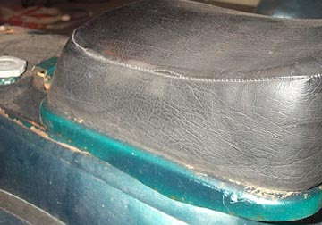
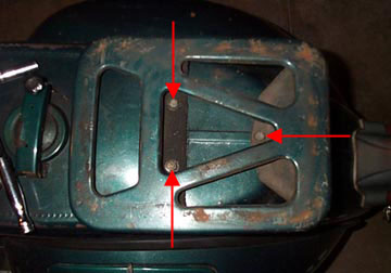
Unfortunately the cable is located inside the frame and the fuel tank will need to be removed. On the Vespa shown in the picture I have a single front seat and a buddy seat on the standard luggage rack. To remove the front seat, use an 11mm wrench to loosen and remove the three bolts into the frame.

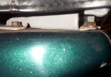
The buddy seat is held to the luggage rack by two 10mm nuts on the bottom side. They are a little difficult to see...

...but a look at the underside of the seat will show them on either side. They hold a small grab bar in place which clamps the seat to the rack. Loosen the nut only enough to rotate the clamp so it passes through the slot.

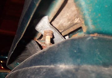
With the rack out of the way you can remove the last three 11mm bolts holding the rack to the frame, and the rear of the fuel tank to the frame.

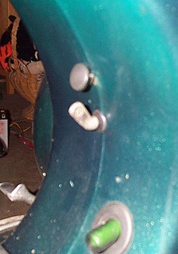
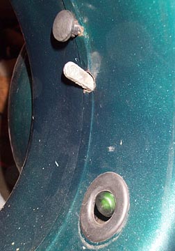
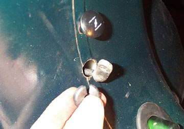
Before you can pull the tank the fuel lever needs to be turned to the on position so it faces up as shown. Also the rubber grommet around the fuel lever shaft will need to be removed by prying it out.

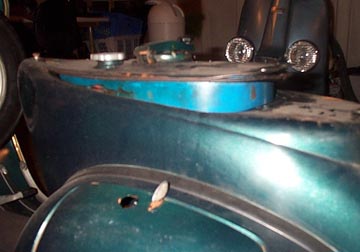
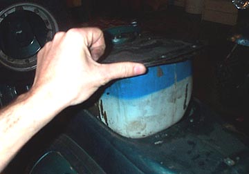
Start to lift the fuel tank up by lifting at the rear....

As you do the oil sight glass (if fitted) and the fuel lever will move backwards and into the frame.

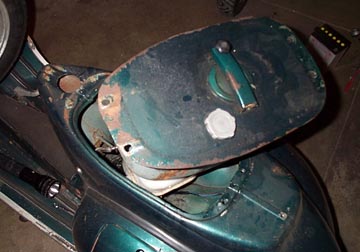
Once the fuel lever passes through the frame hole the tank can be lifted from the frame. Sometimes it will need a little help and you can peer into the frame area and see if anything like cables or fuel lines are being caught.

Usually the fuel line will not need to be disconnected from the tank or the carb. There should be enough length to it to lift and slightly twist the tank as shown above. If you have nice paint work, you might want to protect the edges of the frame opening with a rag.

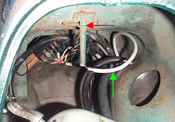
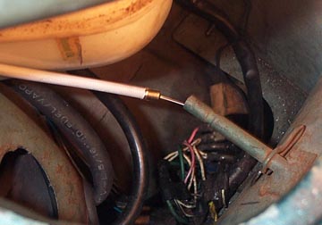
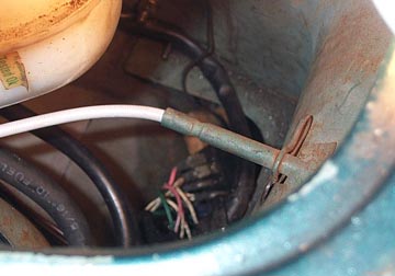
Now you'll be able to see the choke cable (shown with a green arrow) and the frame mounted tube and pin clip in which the small choke plunger fits.

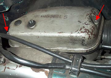
To remove the carb end of the choke cable you'll need to remove the right hand side engine cowl and find the carb box mounted on top of the engine. Using a Phillips screwdriver remove the two screws at either end. Once these are free the top can be removed although it can sometimes need a little effort.

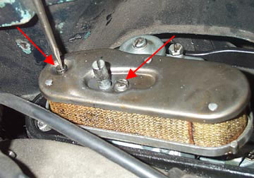
Using a flathead screwdriver, remove the air filter element by removing the two screws. The rear screw is a little weird looking so remember it always goes in the rear hole.

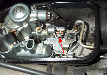
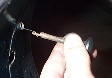
Now you can see where the wire choke cable attaches to the carb. Using a hook of some sort or a flathead screwdriver, unhook the cable and push it out through the hole in the carb box.

Since the carb end is released you can now pull the choke lever beyond the frame and disconnect it from the wire.

Remove the old choke cable and feed it through the hole in the frame. Fit the new choke cable through the frame hole and make sure the end with a loop in it is outside the frame. Push the end of the choke outer cable securely into the end of the frame tube.

Make sure it is fully in the tube or the next step will be very difficult. There is just enough length on the wire to allow you to connect the choke cable.

You'll see the end of the wire poking out of the choke tube on the outside of the frame. The trick is to grab it with some needlenose pliers and....

..thread the wire through the end of choke lever. You can see that one side of the choke lever cut outs is longer than the other (the one on top in this image). Be sure the wire is threaded as shown above to make sure it doesn't come undone in the tube.

With the other end of the cable hanging out through the frame, push the choke lever back into the frame tube. Thread the choke cable through the carb box, and hook it on to the carb hook. Test to make sure the carb hook is all the way released when the choke lever is pushed all the way in, and out when out. If all is well, replace the filter and the carb top.

The final step is to re-fit the rubber grommet around the fuel lever so it doesn't rattle around when driving.

www.scooterhelp.com
Read more...
Gear/ throttle Cable Replacement

This section shows a quick step by step of replacing cables on an older type (pre P-series) scooter. The first step is to remove the headlight unit with two small screws located at about 4 and 8 o'clock when looking at the headlight. The unit can then be hinged out from the bottom and lifted to release a top pin from the headset. The bulb holder can be disconnected by undoing the two metal clasps that attach it to the headlight.

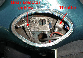
Remove the speedometer by undoing the center of three bolts when looking at the bottom of the headset. The speedo drive and speedo bulb will also have to be disconnected as you pull the speedometer clear. Once this is done you should see something similar to the picture below.

This sections shows how to replace the inner and outer cables for the gear selector box/ throttle slide assuming that the cables are ready for the trash.

I find it is easiest to simply remove the gear end of the twist grip to get the ends of the cables out at the headset end. Using a 10mm socket, remove the central bolt.

Once the pulley is removed, save the spring washer and locating washer that remain on the twist grip end for the rebuild. Move the cables so that the little "top hat" ends to the outer cable disengage from their supports as shown above. Pull the cable inner out of the outer with a pair of pliers. Once it is out you can clip the head of the outer cable to get rid of the crimped metal end as this could get caught as you pull it through the frame.

If you are just removing the inner cable then replace the top hat over the cable outer end, lubricate the new control cable inner with oil, and then thread the new inner in to the existing outer cable all the way until you see it at the selector box end.

If you are also replacing the outer cable you can clip the head of the outer cable to get rid of the crimped metal end as this could get caught as you pull it through the frame as shown in the next few shots.

Clean the end of the old cable outer and wrap in a spiral motion with a piece of electrical tape. This type of tape works well because you can stretch it to make it really tight. Take the new cable outer and place it face to face with the old and continue the wrap around it for about 3 inches. Repeat the process in the other direction (from the new to the old). Once this is secure it should look like the picture above.

At this point a helper is really handy. One person holds the cable at the headset straight up in the air. At the other end you pull the cable slowly through the frame as person number 2 feeds it in. It should slide right through and poke out the proper hole near the engine. The red arrow above shows the old cable outer and the green is the new cable outer. Carefully unwrap the tape from the cables and move on to the next step of threading the inner cable.

Thread both inner cables with the cable top hats in place and set the hats in the support in the headset. Then carefully fit the end nipples in to the pulley in the same direction as they were removed.

Refit the dished washer and then the locating washer, and make sure the small hole in the pulley engages with the peg on the locating washer.

Refit the pulley and tighten the 10mm nut. Place the twist grip in the neutral position and then move down to the selector box end of the cables.

I've switched the model of the bike in the photos but the idea is the same. At the bottom end thread the cable inner around the selector wheel, through the nipple at the end, and then pull it tight. When you pull it make sure the twist grip doesn't move from the neutral position, and be sure the bike is also in neutral at the motor end. Make sure the cable outer is weal seated in the adjuster and that the threaded adjuster is about 1/2 way out so you can adjust it in either direction if needed.

Using a 7mm wrench for the nipple bolt and an 8mm wrench to stop the nipple from turning, tighten the nipple down. It is helpful to have a helper still pulling on the cable to keep it tight. Do the same thing for the other cable and then wiggle the twist grip without actually engaging gears. There should be about an 1/8" of movement. If there is too much movement, equally back out both the adjusters at the selector box. If there is too little, turn them both in enough to get the wiggle.

Note: An alternative to this method to replacing outer cables is to get an extra long control cable from a bicycle dealer (the type used on tandem bikes). Thread it through the new outer cable first so that the nipple is tight against the outer cable end. Then thread the inner in to the old outer cable still in the bike. This will get you the same result as taping the two outers together as shown above. From here, go to the selector box end and place a gear nipple on the inner cable. Now you can pull the old cable outer and the new cable outer will replace it. Once the new cable is in position, remove the nipple and the tandem inner.

www.scooterhelp.com

Read more...

Clutch Cable Replacement

This section shows a quick step by step of replacing a clutch inner cable on a large frame Vespa. To find out where the clutch cable is located at the motor end of the bike, have a friend pull the lever while you watch under the motor to see what moves.

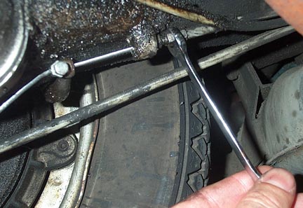
As you can see on this oily example, the clutch cable has been fraying at the pinch point and will soon snap....probably on a rainy night miles from anywhere.

The first step is to remove the existing nipple by using an 8mm wrench on the nipple body and a 7mm wrench on the pinch bolt. Once slackened it can be pulled off the cable, or just cut the cable if it is stubborn and wont come off.

The image above shows the cut cable and the following parts: Red arrow: clutch arm, Blue arrow: adjuster lock nut, Green arrow: threaded adjuster.

To remove the rest of the inner cable, go to the clutch lever and remove the pivot screw while holding the nut below from turning. Some older bikes use a flathead slotted nut on the underside.

With the pivot bolt gone you can remove the lever but be sure to note where the small washers are located so that they can be put back in the same manner. Once the lever is free simply pull on it to remove the inner cable and then disconnect the cable from the lever.

Take the new inner cable and thread it in to the outer housing after a quick lubrication with oil. Be careful not to push the cable outer end back in to the headset. A flashlight is very helpful here. Once threaded push it all the way until you see it poke out at the motor end.

Fit the lever, a little grease, and the washers, and then pull on the motor end until the lever goes back in to position. Fit the pivot bolt and securing nut.

At the motor end make sure the new cable inner goes through the adjuster and the actuating arm. Back out the threaded adjuster so that it is in the middle of its range...meaning you could tighten it or loosen it equal amounts. The image above shows that clutch arm a rest and it is spring loaded.

What is very important to understand is that the clutch arm doesn't actually engage the clutch until further in its travel. Push the arm with your finger towards the front of the bike. You'll feel some resistance and then a very definite stop. This is the green arrow area above. This stop point is where the arm makes contact with the clutch and if you were able to push much harder (in the red arrow area) you'd start to disengage the clutch. Many people have emailed me making the mistake that the initial travel is where the clutch arm is disengaging the clutch.

Slip on the nipple and pull on the cable to make sure the lever at the headset is completely disengaged. Then push the clutch arm forward until the red arrowed point discussed before and tighten down the nipple. I find a very useful tool for this is a set of Vise Grips. You can clamp them just behind the nipple so your hands are free to tighten the nipple with the 8mm and 7mm wrenches without the arm moving back in to the green arrow area.

The final step is to go up to the lever and give it a pull. It should move about an 1/8 of an inch before the arm is in the red arrow zone which you'll feel as the clutch will become harder to pull. If you are in this area then you are good to go. If not you can loosen the clutch adjuster locknut, and either loosen or tighten the adjuster. Once finished tighten the locknut so it doesn't move in the future.

When you take the bike for a test drive, it should be easy to shift and not creep when in gear. To test this change in to 1st gear on flat ground with the clutch fully pulled in. If the bike tries to creep forwards you'll need to back the adjuster out more. If the lever can't hit the grip when fully pulled or if the motor RPM can climb not in rleation to the road speed, loosen the adjuster.

www.scooterhelp.com
Read more...
 

Recent Post